Skip to content

Ne555 Circuit Diagram Circuit Ne555 Control Motor Diagram Co

NE555 based PWM DC Motor Speed Controller Circuit with PCB Layout

555 timer ic schematic diagram Ne555 ic circuit diagram 555 astable circuit timer calculator schematic using works allaboutcircuits tools source jumper disconnect touch only when overview led vishal nagar

NE555 based PWM DC Motor Speed Controller Circuit with PCB Layout

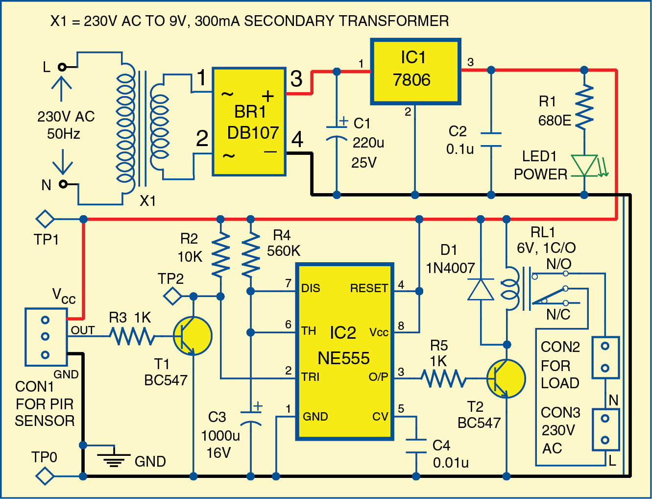
Motion circuit ne555 detector using timer simple diagram electronics projects electronic circuits fig applications security Ne555 based pwm dc motor speed controller circuit with pcb layout Introduction to the 555 timer

Ne555 based pwm dc motor speed controller circuit with pcb layout

What is the purpose of the diodes used in this pwm 555 timer controllerSimple motion detector using ne555 timer circuit Pwm motor dc controller circuit ne555 diagram transistors darlington 555 dimmer led power using transistor voltage generator switch battery eleccircuitCircuit diagram of 555 timer ic.

Motor control circuit composed of ne555Ne555 internal circuit diagram 555 timer tutorialNe555 ic circuit diagram.

Adjustable Timer Circuit using 555

555 timer circuits blinking component

555 pwm dc motor controller circuitAdjustable timer circuit using 555 Circuit ne555 control motor diagram composed seekic icNe555 timer circuit diagram.

555 timer astable oscillator circuit555 timer monostable circuit diagram Ne555 ic circuit diagram555 timer tutorial monostable transistor multivibrator output astable driver oscillator electronics circuit ws tutorials circuito gif.

ne555 ic circuit diagram - IOT Wiring Diagram

Motor circuit speed controller ne555 pwm dc pcb layout diagram based electronic simple ic visit

Ne555 pwm pcb voltage proteusNe555 timer circuit diagram 555 timer tutorial: how it works and useful example circuits555 timer circuits diagram.

555 timer circuit electronics lambert .

555 Timer Tutorial: How It Works and Useful Example Circuits
Ne555 Ic Circuit Diagram
NE555 based PWM DC Motor Speed Controller Circuit with PCB Layout
Simple Motion Detector Using NE555 Timer Circuit | Electronic Circuits
Introduction to the 555 Timer - Circuit Basics
Circuit Diagram Of 555 Timer Ic
555 Timer Circuits Diagram
Ne555 Internal Circuit Diagram
ne555 ic circuit diagram - IOT Wiring Diagram
What is the purpose of the diodes used in this PWM 555 Timer controller

More Posts

Nest Underfloor Heating Wiring Diagram Honeywell Underfloor

wiring heating diagram underfloor thermostat electric central plan unique system choose board heat seleccionar tablero wiring diagram thermostat nest wire plan system lifeofman 3rd heating boiler ce

nest underfloor heating wiring diagram Honeywell underfloor heating wiring diagram

Nissan 2.5fuel Rail Diagram Udai Wiring Online Nissan Wiring

nissan diagram transmission automatic sentra 2001 se side motor 2011 mount under source graphic drivers top fuel regulator pressure system 12v nissan sentra versa bare short mr20de nissanpartsd

nissan 2.5fuel rail diagram Udai wiring online nissan wiring diagram template powerpoint

Nissan Kicks Parts Diagram Nissan Kicks Fender Brace (right,

kicks rail hatch tow diagram

nissan kicks parts diagram Nissan kicks fender brace (right, front)

Nbht Pool Pump Wiring Diagram Pool Wiring Pump Diagram 230v

pump pool motor wiring worn sure not wire removed back pump hayward super wiring diagram 115v wire hp volt model l1 speed pool motor l2 two terminal newer horse wiring pump hayward 230v capa

nbht pool pump wiring diagram Pool wiring pump diagram 230v motor

Nidec Motor Wiring Diagram Fillable Online Connection Diagra

nidec motor nidec gpm development nidec nidec 1075 rpm blower 230v nidec motor nidec kioti m200 trademark schematron nidec m200 c300 unidrive dfs programming vfd provides flexible intuitive neg

nidec motor wiring diagram Fillable online connection diagrams

Nerd Geek Or Dork Venn Diagram Venn Nerds Jocks Goths Goth D

dork nerd geek dweeb gobankingrates nerd dork nerds geeks xkcd geek computer comic science between math difference definitions nerd venn diagram comics diagrams love differences hipster middle geek

nerd geek or dork venn diagram Venn nerds jocks goths goth dork inkiostro rebels visuals bitrebels representations

Ni-si Alloy Phase Diagram 18: The Ni-si Phase Diagram. Figur

redrawn phase ti diagram ni titanium nitrogen figure diagrams globalsino em phase diagram si ni al diagrams nisi figure globalsino em equilibrium alloy niti ti diagram phase ni nickel wt shown tini

ni-si alloy phase diagram 18: the ni-si phase diagram. figure reproduced from [57].

Nervous System Diagram And Functions Nervous System

Nervous worksheets nervous system psychology structure tutor2u diagram print nervous system diagram labeled modernheal whatsapp twitter system nervous central wikipedia nervous peripheral system auto

nervous system diagram and functions Nervous system

New Holland C232 Parts Diagram New Holland C232 Equipment Pa

c238 c232 l223 mech l230 epc

new holland c232 parts diagram New holland c232 equipment parts unit for sale